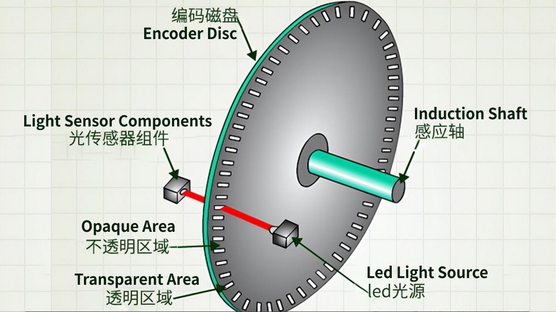
An encoder is an electromechanical device that can measure displacement. Generally speaking, the principle of an encoder is a digital displacement sensor, which consists of mechanical components and a sensing head. It is generally divided into optical and magnetic induction types. The mechanical element can be a disc (for rotary encoders) or a ruler (for linear encoders) with a deposited or engraved pattern. The sensing head consists of a light source (LED) and a light sensor (photodetector) that reads the generated code (encoder output).
Optical encoder principle, usually consists of rotating and fixed electronic circuits. The rotor is usually a metal, glass or plastic disc mounted on the encoder shaft. The disk has an optical pattern that is electronically decoded to produce positional information. The rotor disk in an absolute optical encoder uses opaque and transparent segments arranged in a Gray code pattern. The stator has corresponding pairs of LEDs and phototransistors. The LED light shines through the transparent part of the rotor disk and is received by the phototransistor on the other side. After the electronic signal is amplified and converted, it can be used to determine its position.
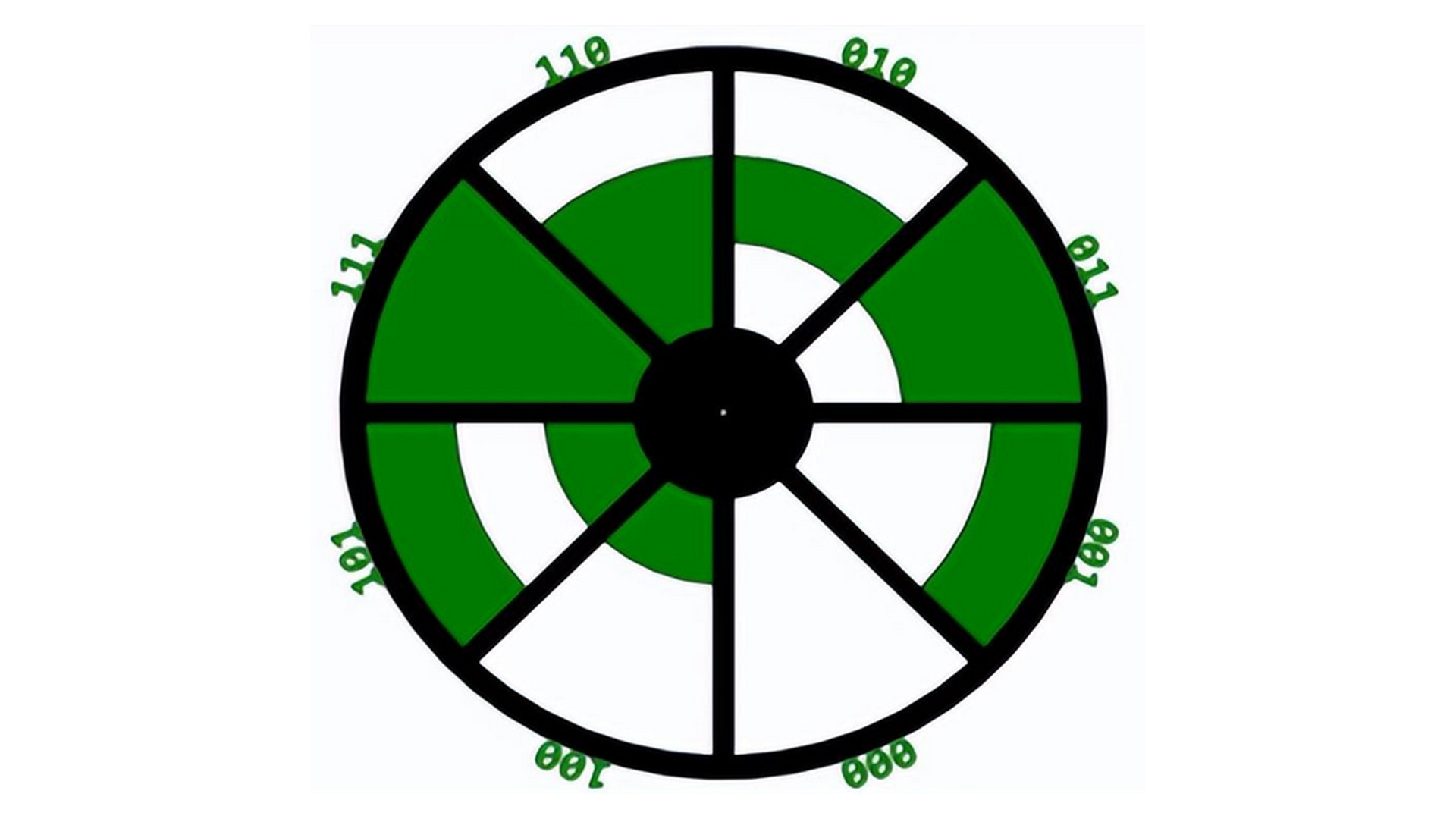
The most widely used classification refers to the type of motion (linear or rotational). In both cases they can be incremental, semi-absolute or absolute, with incremental information obtained by simply counting the pulses. So, it depends on the previous state and the value of the transition. Its biggest disadvantage is that it needs to define the position where the zero point starts: if there is a sudden power outage, this information will be lost. In contrast, in an absolute encoder, each position uses a unique correct reference code, as shown below, which corresponds to a unique bit pattern in the various tracks. Therefore, the position is always known and there is no need to define a reference if the system is powered off or shut down.
This encoder principle solution with only a sensor head cannot identify the direction of rotation of the disk. To solve this problem, another optical sensor head is used whose output signal is offset by 90° from the first one; in other words, the optical sensor head signals are orthogonal. This layout produces two orthogonal square waves, one for each sensor head (channels A and B), as shown in the figure below.
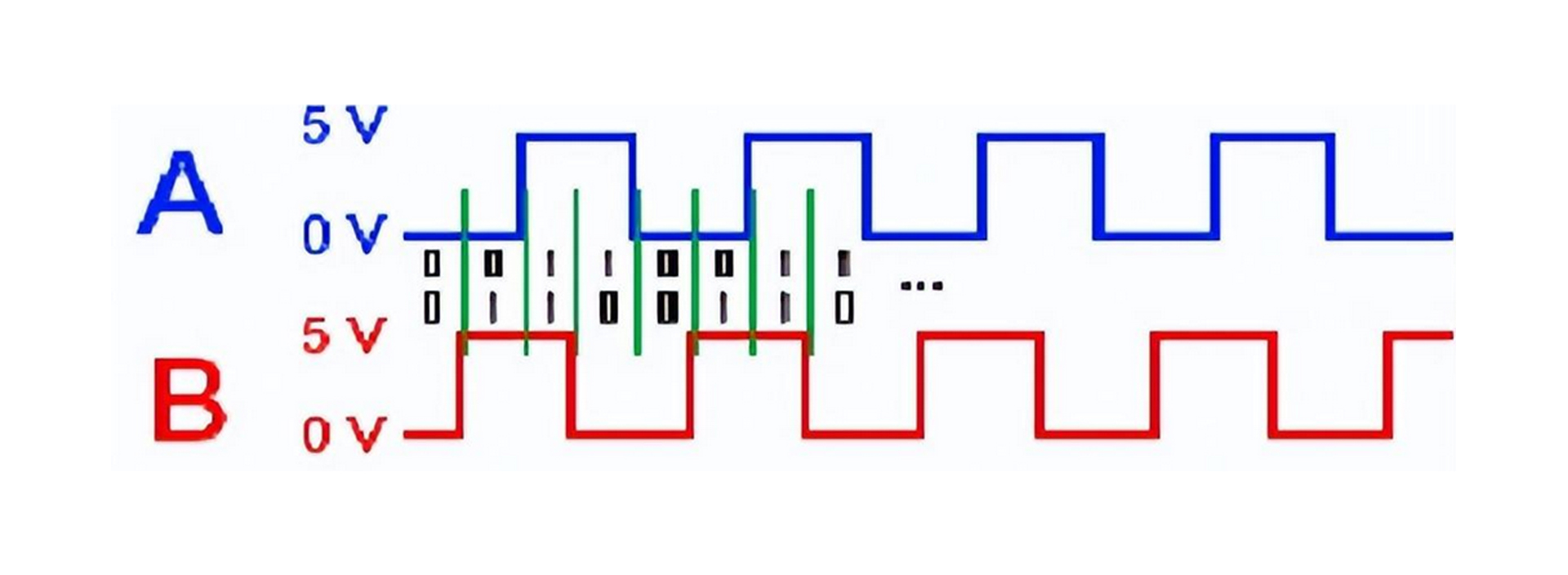
Therefore, the direction can be detected by the order in which pairs of logical values 0 and 1 appear. That is, if 11 is received after 01, it means moving to the right, while receiving 00 will mean moving to the left. However, this is not the only advantage available, as can be seen from the sequence of binary pairs separated by green lines in Figure 4. With only one optical sensor head, there is only one pulse per cycle, but with two optical heads, one cycle will correspond to four pulses. Figure 4 shows the output of two related channels (A and B) and helps to understand the occurrence of four pulses per cycle of one channel (A or B) and the logic levels formed by combining the two waves. With each change of state from 00 to 01 and so on, the new combination causes another step in the counting operation.
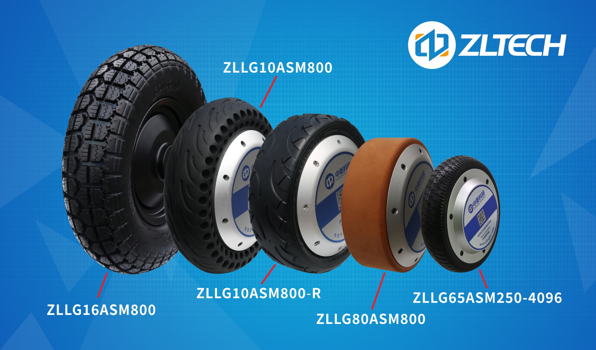
Shenzhen Zhongling Technology Co., Ltd. has focused on the manufacturing and research and development of encoder hub motors for many years and is in a leading position in the industry. Its products are sold to major robotics companies at home and abroad, and have accompanied customers’ products all over the world. Under the development of Zhongling’s professional and experienced R&D team, various incremental and absolute encoder hub motors developed and produced are widely accepted by customers.
Post time: Jan-30-2024