RS485 is an electrical standard that describes the physical layer of the interface, like protocol, timing, serial or parallel data, and links are all defined by the designer or higher-layer protocols. RS485 defines the electrical characteristics of drivers and receivers using balanced (also called differential) multipoint transmission lines.
Advantages
1. Differential transmission, which increases noise immunity and reduces noise radiation;
2. Long-distance links, up to 4000 feet (about 1219 meters);
3. Data rate up to 10Mbps (within 40 inches, about 12.2 meters);
4. Multiple drivers and receivers can be connected to the same bus;
5. The wide common-mode range allows for ground potential differences between the driver and receiver, allowing a maximum common-mode voltage of -7-12V.
Signal level
RS-485 can carry out long-distance transmission mainly due to the use of differential signals for transmission. When there is noise interference, the difference between the two signals on the line can still be used to judge, so that the transmission data is not disturbed by noise.

The RS-485 differential line includes the following 2 signals
A: Non-reverse signal
B: Reverse signal
There may also be a third signal that requires a common reference point on all balanced lines, called SC or G, for the balanced lines to function properly. This signal can limit the common-mode signal received at the receiving end, and the transceiver will use this signal as a reference value to measure the voltage on the AB line. The RS-485 standard mentions:
If MARK (logic 1), line B signal voltage is higher than line A
If SPACE (logic 0), line A signal voltage is higher than line B
In order not to cause disagreement, a common naming convention is:
TX+ / RX+ or D+ instead of B (signal 1 is high)
TX-/RX- or D- instead of A (low level when signal 0)
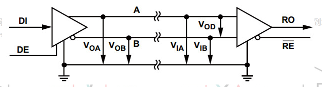
Threshold Voltage:
If the transmitter input receives a logic high level (DI=1), the line A voltage is higher than the line B (VOA>VOB); if the transmitter input receives a logic low level (DI=0), the line A voltage is higher than the line B (VOA>VOB); B voltage is higher than line A (VOB>VOA). If the voltage of line A at the input of the receiver is higher than that of line B (VIA-VIB>200mV), the output of the receiver is a logic high level (RO=1); if the voltage of line B at the input of the receiver is higher than that of line A ( VIB-VIA>200mV), the receiver outputs logic low level (RO=0).
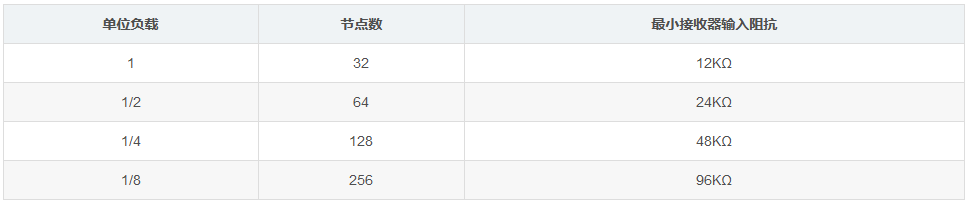
Unit Load (UL)
The maximum number of drivers and receivers on the RS-485 bus depends on their load characteristics. Both driver and receiver loads are measured relative to unit loads. The 485 standard stipulates that a maximum of 32 unit loads can be attached to a transmission bus.
Operating Mode
The bus interface can be designed in the following two ways:
Half-Duplex RS-485
Full-Duplex RS-485
Regarding multiple half-duplex bus configurations as shown in the figure below, data can only be transferred in one direction at a time.

The full-duplex bus configuration is shown in the figure below, allowing two-way simultaneous communication between master and slave nodes.

Bus Termination & Branch Length
In order to avoid signal reflection, the data transmission line must have an end point when the cable length is very long, and the branch length should be as short as possible.
Correct termination requires a termination resistor RT matched to the characteristic impedance Z0 of the transmission line.
The RS-485 standard recommends that Z0=120Ω for the cable.
Cable trunks are usually terminated with 120Ω resistors, one at each end of the cable.

The electrical length of the branch (conductor distance between transceiver and cable trunk) should be less than one tenth of the drive rise time:
LStub ≤ tr * v * c/10
LStub= maximum branch length in feet
v = the ratio of the rate at which the signal travels on the cable to the speed of light
c = speed of light (9.8*10^8ft/s)
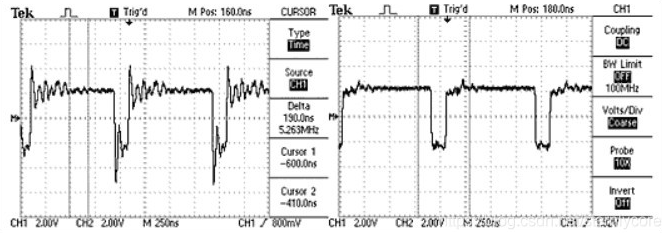
Too long branch length will cause signal emission reflection to affect impedance. The following figure is a comparison of long branch length and short branch length waveforms:

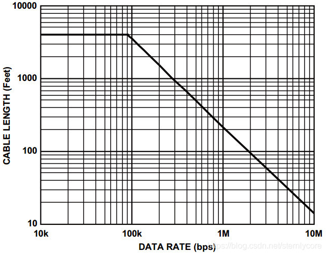
Data Rate & Cable Length:
When using high data rates, only use shorter cables. When using low data rates, longer cables can be used. For low speed applications, the DC resistance of the cable limits the cable length by adding noise margin through the voltage drop across the cable. When using high-rate applications, the AC effects of the cable limit signal quality and limit cable length. The figure below provides a more conservative curve of cable length and data rate.
Shenzhen Zhongling Technology Co., Ltd. (ZLTECH), since its establishment in 2013, has been committed to the wheeled robot industry, developing, producing and selling wheel hub servo motors and drives with stable performance. Its high-performance servo hub motor drivers ZLAC8015, ZLAC8015D and ZLAC8030L adopt CAN/RS485 bus communication, respectively support CiA301, CiA402 sub-protocol/modbus-RTU protocol of CANopen protocol, and can mount up to 16 devices; support position control, speed control And torque control and other working modes, suitable for robots in various occasions, greatly promoting the development of the robot industry. For more information about ZLTECH’s wheel hub servo drives, please pay attention: www.zlrobotmotor. com.
Post time: Aug-04-2022