1. What is back electromotive force?
When a motor is driven to rotate, it essentially becomes a generator. The motor windings rotate in the magnetic field, cutting the magnetic flux lines and generating an induced electromotive force with a polarity opposite to that of the external drive voltage. This is the back electromotive force.
The magnitude of the back electromotive force is proportional to the speed of the motor. The higher the speed, the greater the back electromotive force.
2. Impact of Back Electromotive Force
1. Reduce the effective driving voltage
2. Limit the maximum speed:
As the speed increases and the effective voltage approaches zero, the current also approaches zero, and the torque becomes zero, and the motor can no longer accelerate. This determines the maximum no-load speed of the motor at a given voltage.
3. Generate current surge (commutation surge), which leads to:
1) Breakdown of the driving switch tube (MOSFET/IGBT).
2) Generate electromagnetic interference (EMI), affecting surrounding circuits.
3) Damage to the motor winding insulation.
3. How to deal with back EMF?
1. Increase the power supply voltage or perform magnetic field weakening control
1) Increase the power supply voltage: This is the most direct method. In order to provide sufficient effective voltage to drive current at the desired maximum speed.
2) Field Weakening: For permanent magnet motors, the magnetic field is fixed. Field weakening is an advanced algorithm that intentionally applies a direct-axis current component in the same direction as the back EMF to weaken the internal permanent magnetic field, thereby achieving higher speeds at the same supply voltage. This is commonly used in servo drives and electric vehicles.
2. Use a freewheeling diode or snubber circuit
This is the most common and critical measure to deal with the hazards of back EMF, mainly providing a release path for the induced current.
1) Freewheeling in a half-bridge driver (the most classic structure)
When the low-side switch is off, the motor inductor generates an induced voltage (positive at the bottom and negative at the top) in an attempt to maintain current. This voltage forms a loop through the high-side switch’s body diode (or an external parallel freewheeling diode), feeding energy back to the power supply or dissipating it in the loop resistor. Similarly, when the high-side switch is off, current freewheels through the low-side switch’s body diode.
2) Buffer circuit
Absorbs spike energy, suppresses voltage overshoot, and reduces switching stress and EMI.
3. Energy recovery (regenerative braking)
The energy generated by back electromotive force can not only be consumed but also utilized.
When the motor needs to be decelerated quickly, the drive circuit can be controlled to put the motor into a power generation state. The back electromotive force generated at this time will transfer the electrical energy back to the power capacitor or battery through the freewheeling diode (or actively controlled switching transistor).
4. Soft switching technology
By controlling the switch to turn on or off when the voltage or current is zero, switching losses and voltage and current stresses are fundamentally reduced, which indirectly reduces sensitivity to back EMF spikes.
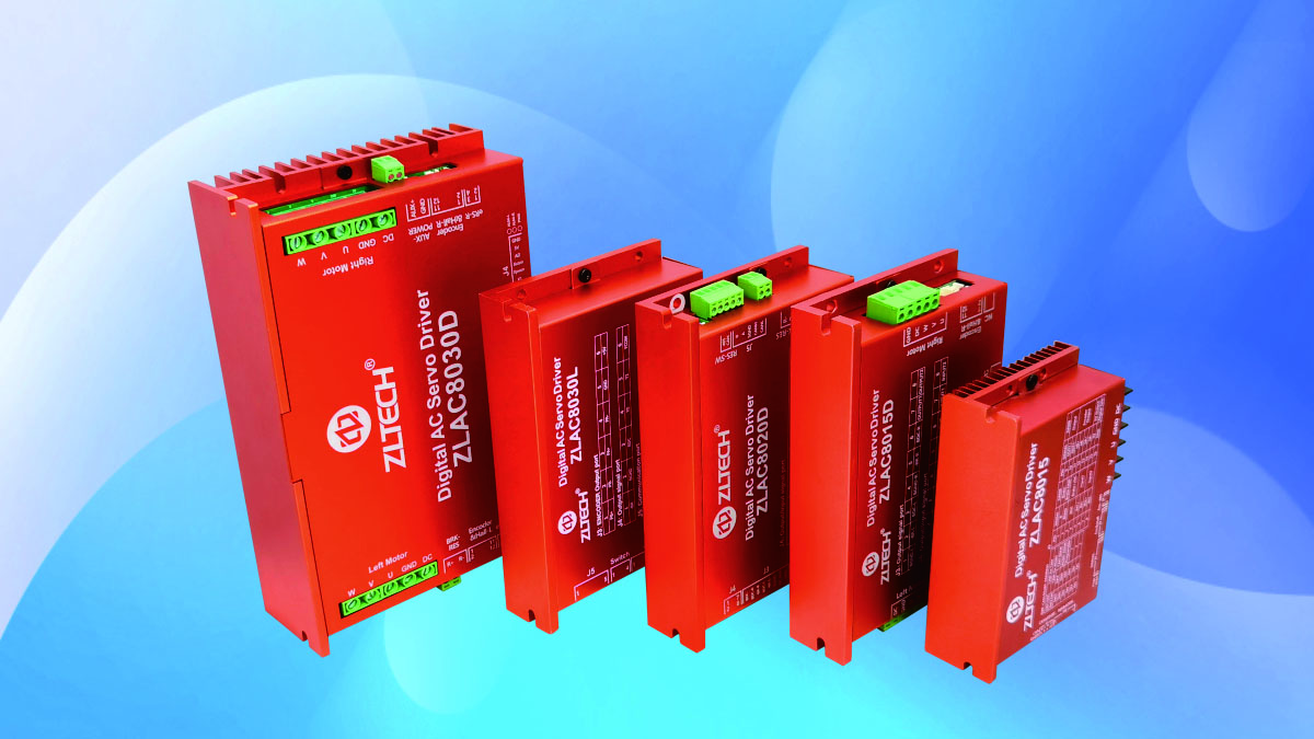
Properly handling back EMF is the cornerstone of stable, efficient, and long-lasting motor operation. Shenzhen Zhongling Technology’s driver features a built-in discharge module that simply and effectively absorbs the back EMF generated by the motor, preventing damage or performance degradation caused by it. For more details, please visit www.robotmotor.com
Post time: Aug-26-2025

